Sunday, August 10, 2008

Certification complete... GREAT SUCCESS!!

Yesterday's flight went swimmingly well despite the complete lack of water on the lakebed :) All photos ©Jaime Fritsch.

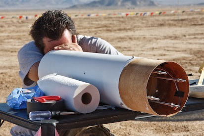
Prepping the recovery system. This was one of Jaime's favorite shots.

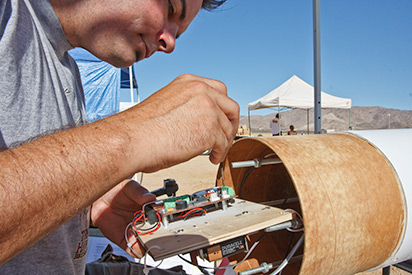
Connecting the electronics board

Stuffing the Rocketman 16 foot chute into the deployment bag is much easier than folding. Very cool system

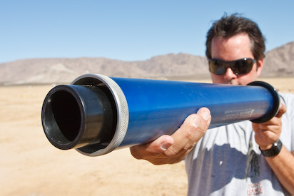
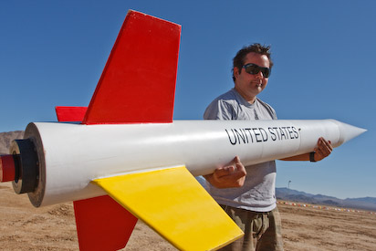
That's a big motor... It's 3" in diameter, almost 2 feet long, and weighs 9 pounds!

Artsy shot

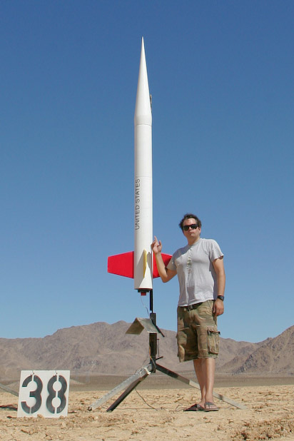
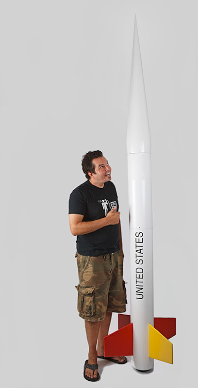
Here I'm trying to hold the almost 10 foot long assembled rocket at 51.1 pounds

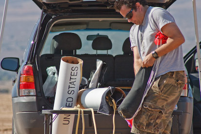
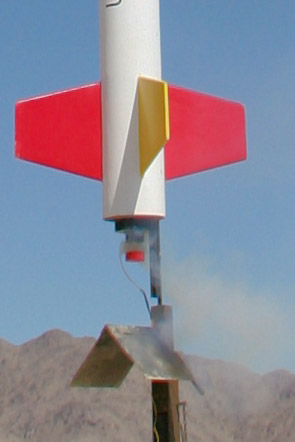
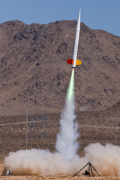
Everything's ready to go. It was a tad windier than I would have preferred but it caused no problems

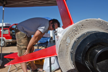
Jaime set up my Canon 1D mark II at a very low angle with a wide lens. From this vantage point he captured some very cool motor details


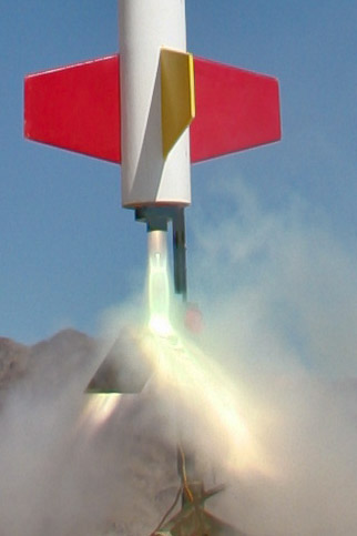
Here's the low angle flight shot. Note the blast debris coming right for the lens. The UV filter was filthy!

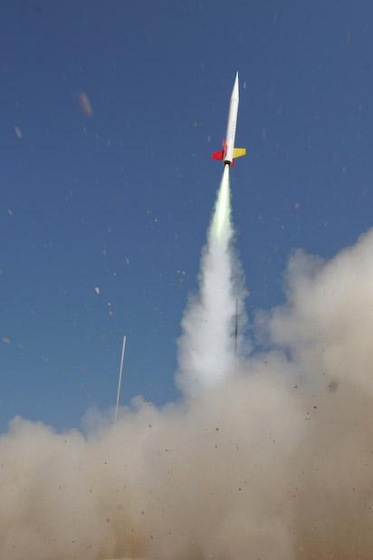
Jaime shot this handheld with the 300 mm f/2.8 lens. I'm surprised how angled the flight appears here because it straightened out for the remainder of the flight. This motor kicks ass and the 51.1 pound beast really bolted into the sky:
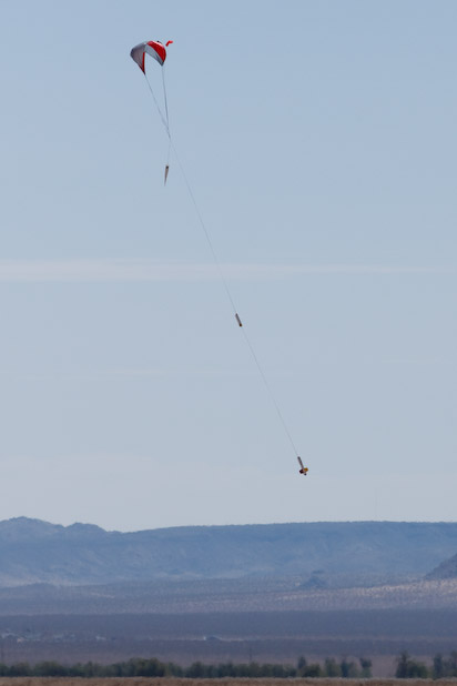
This is a tiny crop of another handheld 300mm shot. You can see the chute has dragged out of the deployment bag:

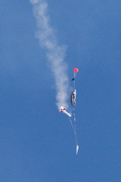
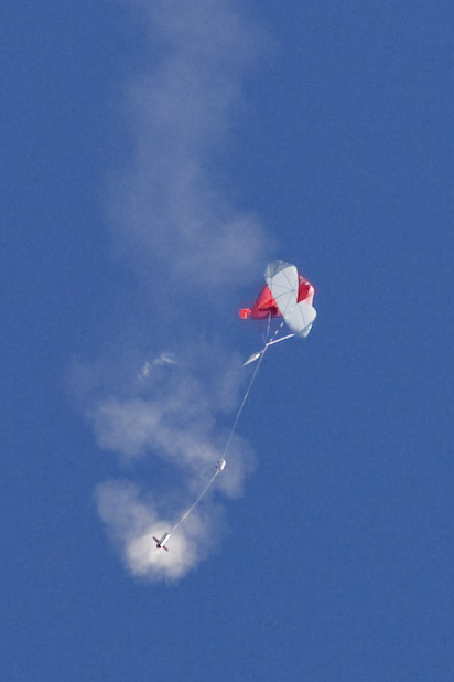
Here the chute has just fully inflated. Everything's looking good.

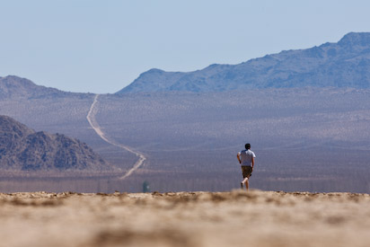
I was quickly walking initially to keep up with the descent. As the rocket decreased in altitude it became obvious that the winds were at lower altitudes so I had to start running to prevent the chute from dragging the rocket along the lakebed after touchdown. Jaime hit the deck to catch this cool shot

That's 65 feet of Kevlar stringing all the goodies together

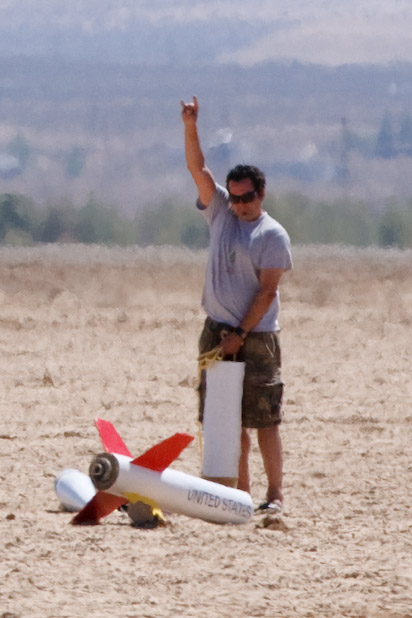
Here I've fully inspected the rocket and everything's intact. Victory!

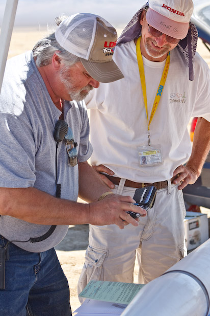
Dok and Kurt signing off on my level 3 paperwork

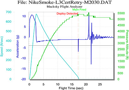
Here's the performance data from the AltAcc2C altimeter

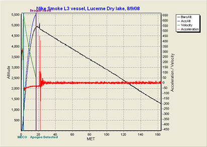
And the data from the ARTS2 altimeter

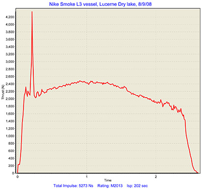
Finally here the motor analysis from the ARTS2. I'm not clear on why that spike occurred early on. Perhaps a propellant chunk shredded off and clogged the nozzle?

I want to thank Jaime for trekking out there with me and shooting photos. I couldn't have done this without his help. Also a big thanks to my TAP members, Dok Hanson and Kurt Gugisberg. I appreciated their kind assistance and patience. Finally thanks to Jack Garabaldi of What's Up Hobbies for lending me his motor casing and for his unparalleled dedication to this hobby.

What's next? Well I spoke to Dok and Kurt and expressed my interest in becoming a Tripoli TAP member for the San Diego club. Right now Tripoli San Diego can only certify level 3 for NAR members so if I became a TAP that would make things easier for everyone. They encouraged me to fly a bunch more M motors, use a wide range of electronics, and to learn hybrid motors. At some point in the future it would be up to Dok and Kurt to recommend me as a TAP member so I'll continue to work on my rocketry "résumé."

Thursday, August 7, 2008

Updated documentation packet

I've completely revamped my documentation packet to reflect all the changes and rebuild details. I've also dropped in this entire blog (minus this entry of course) at the end of the PDF. I think everything's ready to go. Signing off until Saturday with fingers crossed tightly...

All built!

Monday, August 4, 2008

Gap-filled and glassed!

Fiberglassing is becoming less and less painful for me.  I sanded down the primer/paint from the original parts, filled the gaps with epoxy/silica, and applied two wraps of fiberglass.  Both the booster and payload sections went very smoothly.


Tomorrow I'll trim, mask, and prime both sections.  I should be sanding and painting by Wednesday.  I was worried that I'd started too late but this is going really well.  I also need to re-drill the vent holes and static port after painting.  Don't forget!

Sunday, August 3, 2008

Notes on CG/CP, motor selection, and documentation

The repairs to the booster and payload sections will add roughly 9" of extra length overall. This will change both the center of gravity and center of pressure.  I'll measure/recalculate both and update the documentation package prior to Saturday's flight. 

Since I also have to pay full price for the M motor this time (no more L3 cert deals from Aerotech) I'm going to leave my choices open.  I'll do this by generating several Pre-Flight capture forms and matching simulations.  Once I select a motor from Jack at What's Up Hobbies I'll then swap the appropriate pages into my documentation package.

Payload progress

I started by cutting the zippered 8" off the top of the payload section:
After fine tuning via sanding I then cut both coupler and add-on tube to length and employed the same pre-wetting technique as below on the booster:
You can see down into the payload section:
I left 8.5" of non-coupler length inside to accommodate the nose cone shoulder.  Again I verified "squareness" of the new section with the old.  Tomorrow it's gap-filling and fiberglassing.

Electronics switches fixed!

To maximize strength I had planned to drill the switch holes forward of the bulk plate. This would have distanced them from the buckle-susceptible region of the payload section aft of the bulkhead near the tube coupler interface.  I then reconsidered and kept it simple since I had strongly reinforced this otherwise relatively weak region.  You can see that I drilled two holes 120˚ from the vent hole and pushed the switches into them:
Since I was able to find an AltAcc2C altimeter I plan to pull the timer.  As a result I soldered a female power switch connector for the AltAcc (above in rust red).  I'll connect this switch to the board first then slide it in further to attach the switch leads to the ARTS2 altimeter.  I test fit everything before committing to solder and I also put a drop of CA adhesive on each switch hole.  This should keep them from twisting when I'm arming them.  NO MORE HORIZONTAL ARMING REQUIRED!!  :)

Booster progress

I spent most of my Sunday working on repairs.  This entry shows that I sanded the new length of phenolic tubing to fit nicely.  I also had to cut the coupler to 10" from 12" to fit the payload coupler.  I sanded all the parts to be adhered (to improve grip) and mixed up a batch of epoxy.  I took a foam paint brush and coated all key surfaces to ensure good wetting and adhesion.  Finally I twisted/fitted the parts together then taped them up to cure since there were some odd corners that might have otherwise separated during curing:
This shot shows the cured booster with the tape removed:I should also mention that I used a ruler to verify that the new parts were in-line with the old.  I don't want any wiggles or curves during flight.  I'll gap-fill tomorrow then it's on to fiberglassing.

Friday, August 1, 2008

The rebuild commences...

Alright so I've reserved an SUV from Budget for August 8th/9th so I'm feeling the pressure to get these repairs done.  Tonight went really well.  I had started last month by simulating cut lengths using Illustrator.  When I was comfortable with these lenghts I then began with the damaged booster section and marked it all up using a ruler, a tape measure, and an alignment guide.  After marking out the zippered areas I put on a reinforced cutting blade on the Dremel tool and carefully cut out the detritus. This first shot is zoomed out to show the scale of these cuts:
This second is zoomed in to show the markings and cuts:
Finally I marked up a 7.5" phenolic tube with the matching male part to patch this damage. This third shot shows the coupler (not yet trimmed to length) inside the cut area:
Finally this last shots shows how well the parts will mate up.  I need to do some fine tuning but this first phase of repair exceeded my accuracy expectations!:
I'll fine-tune these parts tomorrow night and start on the payload section.  I'm pretty tired now so peace out.

More prep pix from my first attempt

I finally pulled a disc of images that Kristine shot while Doug and I were setting up.  This first shows one of about 20 trips we took back and forth getting everything checked off:
The second is Doug and I setting the rail guides into the rail and setting up the electronics (including my mistake of arming the electronics horizontally!!):
Finally we're examining the setup prior to backing off and firing the beast:
Thanks for documenting, Kristine!

Monday, June 30, 2008

What damage 4 seconds can cause!

I've learned to respect the time unit of one second.  It's amazing how much impact this miniscule time increment can impact our efforts and lives.  I'm getting my second wind on this level 3 thing and tonight I finally committed the zipper damage to blog memory:
Ouch.  That hurts.  The good news is that I'm convinced it'll be better than new when the repairs are complete and that the nose cone remains unscathed.  I plan to cut off all but ~4" of the left tube and roughly half of the right tube.  I'll then epoxy couplers into each and attach a new length of 7.5" airframe tubing.  One cured and fiberglassed the whole rocket will be a bit longer but these repaired joints should be very strong.  
     I'll plan to update my documentation package with a new pre-flight data form and addenda on these repairs.  I'm also gonna make changes to the electronics switches so they can be armed externally.  If Kurt and Dok will be at the July 12th launch at Lucerne I might try again because I'd like to attain my L3 cert before my 40th BD in September.

Sunday, June 15, 2008

Oops! Almost forgot the cool recovery shots!

Kristine must have shot these and they're great but I forgot to tell her I'd switched to manual focus so they could be sharper. That's entirely my fault, however, and I'm grateful she caught 'em!
It all looks fine above right?
Doug's on the left in the foreground and I'm repacking the 'chute in the right background.  You can see my sad face if you squint really hard.  Just kiddin'.

Failure analysis: I think I know what went wrong

I tried to download the numbers from the altimeter today but found no accelerometer data.  The unit obviously had power throughout the flight, however, since the pressure sensor reported a peak altitude of ~4,900 at 17.6 seconds.  Hmmm.  Now I begin re-reading the ARTS2 altimeter manual and I figured out the problem: the unit must be armed when the rocket is in a vertical position!  This may seem obvious but we literally had no other safe way to arm the electronics so this change of plan made sense at the time.  Here's my best guess at a sequence of events:
  • I armed the electronics in a horizontal position so the altimeter's accelerometer never calibrated or started measuring.  In retrospect I thought I'd heard it beeping correctly but I must have been wrong.
  • Since the altimeter requires acceleration data to fire the ejection charge nothing happened at peak altitude.
  • I had set the timer for 22 seconds based on a simulated delay of 21.5 seconds but the actual barometric peak occurred at 17.6 seconds.  This means the rocket continued to arc over for 4.4 seconds longer than was required.
  • This extra speed combined with the extremely heavy rocket parts must have caused the zippers.
When I attempt to certify again I plan to:
  • Move the switches to the exterior of the payload section so the rocket can be easily armed in a vertical position.  I'd originally designed around this because I wanted to avoid drilling holes and weakening the critical sustainer/payload area.  I also didn't want to risk lengthening the switch wires adding complication. I feel much better about all this now and the switches will mount in the payload section not the top of the electronics bay as originally feared.
  • I'll replace the 1/2 " tubular nylon with 1/2" Kevlar with stitched end loops to improve strength after ejection.
  • I'll add two Giant Leap "fireball" anti-zipper pads to both shock cords.
I look forward to another "attempt at success" in fall of this year.

Flight day... Yay then boo!

Alright so first off I want to thank Kurg Gugisberg and "Dok" Hanson for acting as my Technical Advisory Panel members.  I also want to thank my buddy Doug for helping me drag this beast around the lakebed in the heat all day.  His son Brandon shot video of the flight and my friend Kristine shot photos and toted my tripod/1Ds mark III/300mm f/2.8 IS lens around in the sun for hours.  I'm grateful to all of you and this certification attempt wouldn't have been possible without you!
       I rented a minivan on Friday and had it loaded up by about 10PM that night.  Doug, Brandon, and I headed out at 5:50AM the next morning, encountered no traffic, and touched down at Lucerne Valley dry lake bed at 8:25AM.  There was NO wind which is a small miracle these days.
       I immediately headed over to Jack Garibaldi's "What's Up Hobbies" trailer to borrow the 75 mm/5120 N•s casing for my cert flight.  Someone else had beat me to it so I dropped back and prepped everything but the motor.  The electronics wiring and payload assembly came together without a hitch.  I then took the partially assembled rocket over to "Dok" to check the build and authorize the flight.  He looked through my documentation and asked "What's the thrust in pounds of the motor you're flying?"  I froze up a bit because I knew that answer but it wouldn't come to me.  I offered "1297 newtons divided by 4.45 N/pound-force... now if I only had a calculator."  Dok was fine with that answer and after an inspection authorized me to fly.  I then needed the same checkout by Kurt but, sadly, he'd just crashed a very beautiful/complex project and was just heading out to pick up the debris.  I felt so bad for him!  It's so painful to work that long on something, one little thing goes wrong, and the whole thing goes down.
     Now I'm waiting for someone to announce a level 3 certification attempt on an M1297 because this will tell me who has the casing I need.  At about 11AM I hear that Jim Hawk is flying his Polecat Aerospace Army Hawk rocket on an M1297 for a level 3 cert attempt.  Bingo. His flight appeared beautiful to me.  I wandered over to find Jim and let him know that there was no rush but I needed to borrow the casing whenever it was cleaned.  At this point I'm starting to feel a breeze and I begin panicking because the wind almost never subsides once it starts in the desert. Unfortunately Jim suffered a failure known as a 'zipper' where the shock cord tears through the body tube due to the extreme ejection forces involved.  One very important element of any certification attempt is that the rocket be recovered ready to fly without repair so Jim had failed to certify.  After about 20 mins Jim handed the casing over to me and I ran back to prep the motor.
     It's amazing that this huge motor is much easier to assemble than than a hobby store motor! It's a very elegant design and it was built and loaded into the rocket in no time.  The final weight was ~47 pounds with the motor.  Doug was concerned that the whole thing was too heavy and I must admit I was also a bit concerned that all my simulation work was inaccurate.  In the end I trusted Rocksim and we carried the rocket over to Kurt for examination.  He said that the 1/2" tubular nylon included with the kit was small for a level 3 attempt and offered his 1/2" kevlar cord to be attached in parallel as a reinforcement.  After this he signed my paperwork and we proceeded from the range safety officer to the launch control officer and out to the pad.
       Doug and I loaded up the rocket on the launch rail in a horizontal position.  After tilting the rocket to vertical I found that my original plan to pull the payload section off and arm the electronics would not work without a stool to increase my height.  We then moved the rocket horizontal again, armed the electronics, and re-raised the rail.  I installed the igniter and we were all set.
       After some additional waiting the launch control officer announced my flight at about 1PM. The wind had oscillated between 0 and 8-10 mph so I'm stressing at this point.  Right before launch the wind calmed down and the flight was beautiful!:
The delay seemed a bit long to me but everything looked fine as the parachute ejected and inflated.  I was elated!  I ran about 1/2 mile out to the rocket now on the ground only to discover that I'd zippered both tubes!! Dammit!   How had this happened?  I'd never zippered a single rocket in 32 year of flying rockets.  Did it HAVE to happen now?!  Apparently so.  It's interesting to note that the altimeter was not beeping out the altitude as it should have been.  Doug and I carried the damaged rocket back and I had to tell Kurt that I'd failed.  
     I'm convinced that I'd done everything I could to fly successfully so I'll need to do some thinking to determine root cause.  I was planning to buy another kit to try again but I had an epiphany while standing in line: I can rebuilt it better than it was. Better. Stronger. Faster.  As such I purchased two 48" lengths of 7.5" diameter phenolic tubing and three 12" long coupler tubes.  I'm thinking the rebuild should be comparatively quick and should also allow me to put the video camera back in.  Yay!  Wish me another round of luck for October or November of this year, por favor.

Finished, painted beast.

Thanks to my buddy Doug Vannier for shooting this:

Electronics board

Here's the final physical electronics board layout:
The two holders on the left and the two-sided foam tape on the right will hold the three 9V batteries.  I'll also bind all three on the board with zip ties hence the four holes on each side of each battery.

Friday, June 13, 2008

And......... done.

Having arisen at 3:45 this morning I'd certainly hoped to do more posting today.  However we had a company picnic and I was working all day to finish this project up so you'll have to trust that it's now finally complete.  I plan to post the final pics of the electronics board, and the final version of the doc package later tomorrow night or Sunday.  Fingers crossed for some killer flight and recovery shots as well.  I also hope to get some quality HDV video so I'll try to throw that somewhere.  Wish me luck tomorrow!

"Modern High Power Rocketry 2" book

I'm putting the finishing touches on the big "torpedo" as one friend calls it and was searching for the latest information on vent hole and static port sizing.  These holes are drilled into the airframe to acclimate internal and external pressure and prevent failures.  In any event a Google search revealed an almost complete preview of the book Modern High Power Rocketry 2 by Mark Canepa.  I marvel at how thorough this 'preview' is and was so impressed with the content I bought it from Amazon on the spot.  Great stuff, Mark!

Tuesday, June 10, 2008

Documentation packet v2

I just completed an extensive revamp of my documentation packet [updated 8/8/08].  Changes/additions in red include:
  • I corrected the CAD rendering on the TOC page to reflect the actual sustainer tube length of 40".
  • I corrected two schematic wiring errors
  • I added a flight simulation section based on Rocksim simulations using the latest Lucerne Valley weather and Google Earth coordinates and elevation data.
  • I authored my detailed flight plan
  • I added a packing list (don't want to forget anything!)
  • I edited my build plan to reflect changes and additions now that I'm very nearly done.
After Dok/Kurt review and approve this document I'll publish a final version before Friday and print this beast out so I can carry a book out with me.

Rail guides

I was all hot to prime the sustainer and finish this beast but I'm glad I lagged because I almost forgot the rail guides!  These standoffs will compensate for the nose cone bulge near its bottom and prevent scraping during liftoff.  I designed this airfoil-shaped standoff to be cut from 1/2" plywood:


The top shape is the top view and the bottom is the cross section showing the curvature to match the 7.67" diameter tube.  I traced the top design on plywood and did a rough cut using my bandsaw.  I then finished the top-down shape using my disc/belt sander.  I then used the curved end of the belt sander to form the curvature of the bottom shape.  
    I center punched the hole in the top and drilled a 1/8" hole through it.  I then marked the sustainer tube both 4" and 29.25" from its bottom (into the centering ring plywood) using a 90˚ strip of extruded aluminum and center punched markers there.  I drilled a hole in each 1.1" deep and sanded the area around these holes.  I applied epoxy to the bottom of the standoff, mashed it down on top of these holes, and screwed 1-3/4" machine screws through the rail guide/standoff and into the 1.1" holes.  Since these assemblies will need to support 40+ pounds of weight they had to be solid and I'm confident I achieved that goal:

Fiberglassing for fun a profit

A wise manager at work once said "if you work on something it gets better."  He was really speaking of working on issues but I think this applies to me since fiberglassing used to be an issue for me.  As I progress toward the end of this project I'm feeling really good about the journey and the improvement of several of my skills.
    I created a rectangular template in Illustrator (21" x 50") and used it to cut a single piece of glass cloth at a 45˚ angle, again for maximum strength.  After masking the shoulder of payload section with masking tape I laid this cloth strip on the tube and tacked it in place with a few brush loads of epoxy.  It's interesting that the 45˚ cloth deforms in a way that makes it difficult to maintain adequate width and coverage on the 20" payload tube.  I had to continuously stretch the cloth to width every 6" of length or so.  I also learned to brush downward at a 45˚ angle rather than across or lengthwise.  This makes sense in retrospect but I had to figure it out on the fly.  When I'd applied the total length of cloth (2.1 wraps worth) I then squeegeed the excess resin out of the layers.  This minimizes weight without detriment to strength:
I think you can tell that this is an extremely uniform layer.  Next I started on the upper portion of the sustainer but this time I chose 0˚ cloth rather than 45˚.  The reason is that the majority of this 40" long tube is filled with either motor rube/rings or the coupler of the payload section.  There's only about a 4" gap in the tube so I don't really need the extra strength of the 45˚ hassle.  I applied the same technique as above and here's the result:
I allowed both to cure and they're über tough now.

Kilz does!

Meet my new favorite rattle-can product:
I read an article on "easy fiberglassing" and in the last paragraph they mention this Kilz spray primer.  It's really amazing stuff because it's thick and soupy but exhibits excellent cohesion and doesn't run when you really lay it on.  It quickly fills sizable gaps and dries quickly leaving a thick layer of material.  It also sands easily so, all of sudden, it's easy to produce very smooth finishes quickly.  Git sum.

Tubular nylon linkages

While waiting for some other parts to cure I secured quick links to each end of both 30 foot lengths of tubular nylon:

I leveraged the Public Missles technique of:
  • tying a triple square knot (it's probably called something else, however)
  • applying a couple of drops of CA adhesive to tack the knot in place
  • applying epoxy to the two nylon interfaces at each end
  • wrapping three pieces of gaffer's tape along these two lengths of nylon at each end to bind them together
  • placing a clamp near the knot at each end
  • allow to cure
Since these assemblies will tether together the sustainer/payload and payload/nosecone it's extremely important that they be robust; hence the overkill on knotting and bonding.

Friday, June 6, 2008

Final internal reinforcement

I've seen many a high-power rocket fail at the coupler between the payload and sustainer sections.  Many folks forget to reinforce the inside of the coupler so that's the weak point that buckles under the tremendous forces of flight.  I cut three 2" wide strips of 45˚-oriented glass, soaked them in epoxy, wrapped them one at a time around a 3/8" dowel, then unwound each inside the coupler against the forward bulkhead:
I pressed all three layers down onto each  other and I think you'll agree that looks much stronger than a bare piece of phenolic tubing.  Keep in mind that the bottom of that bulkhead is about 1" above the payload/sustainer interface so I think I have things covered.
     I also repeated the above procedure as the final reinforcement in the nose cone.  I poured one more pool of epoxy in there and now the nose cone is really ready to finish.